 |
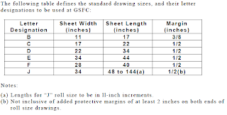
| Standard Drawing Size |
 |
| Format Standard Drawing |
 |
| Standard Drawing Line |
General information for the selection or development of a drawing title is as follows:
- The title should be as brief as possible but should contain sufficient information to categorize the part properly and to distinguish it from other similar parts.
- The drawing title shall consist of the following :
- Identifying noun or noun phrase.
- The most significant modifier or modifying phrase.
- The next most significant modifier or modifying phrase.
The noun or noun phrase establishes a basic concept of an item. The modifiers serve to narrow the area of concept established by the basic name. A modifier is separated from the noun or noun phrase by a comma and from any preceding modifier by a comma. The type designator and/or any additional modifiers required to further identify an item are separated from the first part of the title by a dash. Where applicable, the word “ASSEMBLY” shall be used as the last word of the noun phrase.
EXAMPLES:
“Beam, Hoisting, Guided Missile”
“Cover, Protective, Rocket Motor—Forward Section”
“Cabinet, Electrical Equipment—CY-147”
“Transportation—Dolly Assembly, Earth Satellite”
EXAMPLES:
“Beam, Hoisting, Guided Missile”
“Cover, Protective, Rocket Motor—Forward Section”
“Cabinet, Electrical Equipment—CY-147”
“Transportation—Dolly Assembly, Earth Satellite”
- The noun, or noun phrase, is never abbreviated. Abbreviations are used in the modifiers only when space is limited. When used, abbreviations shall conform to Abbreviations, paragraph 2.2 on page 12.
- When one drawing supersedes another, the new drawing, when practical, has the same title.
- Parentheses are not used to enclose any portion of the drawing title.
- Program names (or abbreviations) should be added to the “Used On” block and not the Title block; exceptions are on the final or top assembly drawing.


0 comments:
Post a Comment